Novastar H-Series H5 Main Frame Video Wall Splicer for 39 Megapixels

The Novastar H-Series H5 Main Frame Video Wall Splicer is an advanced video processing solution designed for creating large-scale displays with up to 39 megapixels of resolution. This powerful splicer provides a range of features and capabilities that make it an ideal choice for professional applications where high-quality digital video playback is essential.

All information about the product
  • Supports up to 39,000,000 pixels, 10 input cards, and 3 output cards
  • Supports redundant power supply
  • HDR10, HLG, and 10-bit processing
  • Web Control

د.إ13,475.00

The Novastar H-Series H5 Main Frame Video Wall Splicer is an advanced video processing solution designed for creating large-scale displays with up to 39 megapixels of resolution. This powerful splicer provides a range of features and capabilities that make it an ideal choice for professional applications where high-quality digital video playback is essential.

The Novastar H-Series H5 Main Frame Video Wall Splicer features advanced image processing capabilities, including pixel-level brightness and chromaticity calibration, which ensures that your video wall displays accurate and vibrant colors at all times. The splicer also includes support for multiple input signal formats, including DVI, HDMI, and SDI.

Other key features of the Novastar H-Series H5 Main Frame Video Wall Splicer include:

  • Support for up to 4K UHD resolution.
  • Multi-screen stitching capabilities for seamless image display across multiple screens.
  • User-friendly control interface with remote control options.
  • Advanced error detection and correction capabilities for reliable operation.
 

Overall, the Novastar H-Series H5 Main Frame Video Wall Splicer provides a reliable and efficient solution for creating high-quality video walls with exceptional clarity and color accuracy. Its advanced image processing capabilities and support for multiple input signal formats make it an ideal choice for a wide range of professional applications where reliable and high-quality digital video playback is crucial.

 
All information about the product
  • Supports up to 39,000,000 pixels, 10 input cards, and 3 output cards
  • Supports redundant power supply
  • HDR10, HLG, and 10-bit processing
  • Web Control
Technical data:
RS-232: 1
Input Slots: 10
Output Slots: 3
Scaling Function: Yes
Crop Settings: Yes
Layers: 48
GenLock: In & Out
Maximum Loading Capacity: 39000000 px
Controlling Mode: Ethernet / RS232
Power Supply: 100-240 VAC 50-60 Hz
Power Consumption: 400 W
Power Connector in: IEC C13 female
Data Connector in: RJ45
Data Connector out: RJ45

Change History

Document Version Release Date Description
V1.8.0
2023-02-17
Added the description of the H_4xfiber sending card.
V1.7.0
2022-12-05
  • Added the descriptions of the H_4xDVI output card, H_4xHDMI output card and 0 output card.
  • Updated the decoding capability description of the H_2xRJ45 IP input card.
V1.6.0
2022-04-30
  • Added the section of Notes and Cautions.
  • Updated the certifications.
  • Added the description of the H_1xDP1.2 input card.
V1.5.2
2021-08-30
  • Added the description of the low latency function.
  • Added the notes for use of the USB connectors and COM port.
  • Updated the certifications.
V1.5.1
2021-06-10

Added the description of ordering or purchasing the optical module for the H_16xRJ45+2xfiber sending card.

V1.5.0
2021-04-30
Added the description of the H_1xHDMI2.0 input card.
V1.4.0
2021-03-31
  • Added the descriptions of the H_1x12G SDI input card and 0 output card.
  • Added the descriptions of the following new features:

−    XR scenario control

−    Device backup and LED 4K sending card backup

V1.3.1
2021-01-08
Added one HDMI cable to the product accessories.
V1.3.0
2020-11-30
  • Added the description of the H_STD I/O card.
  • Deleted the maximum screen quantity and added the maximum layer quantity in the specification table.
  • Changed the maximum widths and heights supported by the dual-link DVI and HDMI input and output connectors.
V1.2.0
2020-09-04

Added the descriptions of the following cards:

  • H_2xDP1.1 input card
  • H_20xRJ45 sending card
V1.1.1
2020-08-20

Updated the maximum height supported by the H_16xRJ45+2xfiber sending card to 10240 pixels.

V1.1.0
2020-07-31
  • Added the descriptions of the following new functions:

−    Eye saver mode on Web page

−    3D function

−    Input source grouping and decimal frame rates

−    App control on the pad device

  • Added the descriptions of the following input cards:

−    H_4x3G SDI input card

−    H_2xCVBS+2xVGA input card

−    H_4xVGA input card

V1.0.1
2020-06-02

Updated the description of the H_2xRJ45 IP input card.

V1.0.0
2020-05-15
First release

Introduction

The H5 is NovaStar’s newest generation of video wall splicer, featuring excellent image quality and designed especially for fine-pitch LED screens. The H5 can work as splicing processors that integrate both video processing and video control capabilities, or work as pure splicing processors. The whole unit adopts a modular and plug-in design, and allows for flexible configuration and hot swapping of input and output cards. Thanks to excellent features and stable performance, the H5 can be widely used in a variety of applications, such as energy and power, judicial departments and prisons, military command, water conservancy and hydrology, meteorologic earthquake prediction, enterprise management, metallurgy of steel, banking and finance, national defense, public security traffic management, exhibitions and presentations, production scheduling, radio and television, educational and scientific research, as well as stage rental applications.


Based on the powerful hardware FPGA system architecture, with a modular and plug-in design, the H5 features a stable and highly efficient pure hardware architecture, and provides a variety of connector modules for flexible and personalized configuration, allowing for easy maintenance and low failure rate. The H5 provides the industry-standard input connectors, including HDMI, DVI, DP, VGA, CVBS, SDI and IP, and supports 10-bit video source input and processing, as well as 4K high-definition inputs and outputs. The H5 also provides two kinds of LED 4K sending cards, allowing for the backup between the OPT ports and Ethernet ports as well as ultra-long distance transmission. Moreover, the H5 supports multi-screen and multi-layer management, input and output EDID management and monitoring, input source renaming, BKG and OSD settings and more, bringing you a rich image construction experience.


In addition, the H5 adopts the B/S architecture and supports cross-platform, cross-system access and control without the need to install an application program. On a Windows, Mac, iOS, Android or Linux platform, online collaboration of multiple users is supported and the Web page response speed is very fast, which greatly improves on-site setup efficiency. What’s more, the H5 supports online firmware update, allowing for easy hardware update on a PC.

Certifications

CE, UKCA, FCC, IC, UL, CB, NOM, RCM, KC, CMIM

If the product does not have the relevant certifications required by the countries or regions where it is to be sold, please contact NovaStar to confirm or address the problem. Otherwise, the customer shall be responsible for the legal risks caused or NovaStar has the right to claim compensation.

Features

Modular and plug-in design, free combination at your will

  • Three kinds of LED 4K sending cards

−       H_20xRJ45 sending card loads up to 13,000,000 pixels.

−       H_16xRJ45+2xfiber sending card loads up to 10,400,000 pixels and provides two OPT ports that copy the outputs on Ethernet ports.

−       H_4xfiber sending card loads up to 20,800,000 pixels and supports three working modes, including independent, copy and backup.

  • Multi-capacity configuration on a single card slot

−       4x 2K×1K@60Hz

−       2x 4K×1K@60Hz

−       1x 4K×2K@60Hz

  • Simple screen configuration using a single card and connector
  • Online status monitoring of all input and output cards
  • Hot-swappable input and output cards
  • H_2xRJ45 IP input card supports up to 512 IP camera inputs and input
  • Auto decryption of HDCP-encrypted sources
  • Decimal frame rates supported
  • HDR10 and HLG processing

Multi-screen management for centralized control

  • Each screen can have its own output
  • Output mosaic

Adopts the frame synchronization technology, which ensures all the output connectors output the image synchronously, and the image is

  • Input source grouping management
  • Eye saver mode

complete and played smoothly, without any stuck, frame loss, tearing or piecing.

  • Irregular screen configuration

Supports irregular rectangle mosaic without any limitations.

Display the image in a warmer but less bright way to relieve eye strain.

  • LCD bezel compensation

Diverse display possibilities for flexible configuration

  • Multi-layer display

A single card supports 16x 2K layers, 8x DL layers or 4x 4K layers.

All layers support cross-connector output and the layer quantity is not reduced for cross- connector output.

  • High-definition scrolling text

Customize the scrolling text content, such as slogans or notification messages, and set the text style, scrolling direction and speed.

  • Up to 2,000 presets

Fade effect and seamless switching supported, less than 60ms preset switching duration

  • Scheduled playback of preset playlist

Set whether to add the presets to playlist, which is ideal for monitoring, exhibitions, presentations, and other applications.

  • OSD settings on a single screen and adjustable OSD transparency
  • BKG settings

BKG images do not occupy the layer resources.

The max. width and height of a BKG image is up to 15K and 8K respectively.

  • Channel logo management

Set a text or image logo for identifying the input source.

  • Input source cropping and renaming after cropping

Crop any input source image and form a new input source after cropping.

  • HDR and 10-bit video processing, allowing for a more exquisite and clear image
  • Color adjustment

Output connector color and screen color adjustable, including the brightness, contrast, saturation, hue and Gamma

  • XR scenario control
  • 3D function

Work with NovaStar’s 3D emitter – EMT200 to enjoy the 3D visual effect.

  • Low latency

Reduce the latency from the input source to the receiving card to as low as 1 frame.

Web-page control, easy, friendly and convenient

  • Web control

Real-time response and 1000M/100M self- adaptive network control, allowing for multi-user collaboration

  • Monitoring of inputs and outputs on Web page
  • Firmware update on Web page
  • Ark Visualized Management and Control Platform app control on pad device

Status monitoring and redundant power supply for better stability and reliability

  • Self-test for fault detection
  • Auto monitoring and alarms

Supports hardware monitoring, such as fan rotation speed, module temperature and voltage, running status, and sends fault alarms if necessary.

  • Supports an optional power supply for higher system
  • Backup design

−       Backup between devices

−       Backup between LED 4K sending cards

Appearance

Front Panel

*The picture shown is for illustration purpose only. Actual product may vary due to product enhancement.

Notes:

  • This product can only be placed Do not mount vertically or upside-down.
  •  The product can be mounted in a standard 19-inch rack capable of withstanding at least four times the total weight of the mounted Eight M5 screws should be used to fix the product.
Name Description
LCD screen

Touchscreen displays the menus, submenus and messages, as well as device status and monitoring information, and allows you to perform all the operations at your fingertips.

Rear Panel

*The picture shown is for illustration purpose only. Actual product may vary due to product enhancement.

Notes:

  • The silkscreen marking “I-x” indicates the slot is dedicated to the input card. “I” stands for input and “x” stands for the slot For example, “I-1” indicates this slot is the 1st input slot and for installing an input card only.
  • The silkscreen marking “O-x” indicates the slot is dedicated to the output card. “O” stands for output and “x” stands for the slot number. For example, “O-10” indicates this slot is the 10th output slot and for installing an output card only.
  • The silkscreen marking “MVR” indicates the slot is dedicated to the preview card
Input Card
H_4xDVI input card

Support for single link and dual link input modes, and 10-bit input source HDCP 1.4 compliant

Does not support interlaced signal input.

  • Single link mode:

−    Four DVI connectors are all used for input.

−    Each connector supports the maximum resolution of 2048×1152@60Hz and the minimum resolution of 800×600@60Hz.

−    Custom resolutions:

Max. width: 2560 pixels (2560×972@60Hz)

Max. height: 2560 pixels (884×2560@60Hz)

  • Dual link mode:

−    Connectors 2 and 4 are used for input, and connectors 1 and 3 are unavailable.

−    Each connector supports the maximum resolution of 3840×1080@60Hz and the minimum resolution of 800×600@60Hz.

−    Custom resolutions:

Max. width: 3840 pixels (3840×1124@60Hz)

Max. height: 4095 pixels (1014×4095@60Hz)

Status LEDs:

  • On: The input source is accessed normally.
  • Off: No input source is accessed or the input source is abnormal.
H_4xHDMI input card

Support for 10-bit input source

Does not support interlaced signal input.


For HDMI 1.3 inputs:

  • Four connectors are all used for input.
  • Each connector supports the maximum resolution of 2048×1152@60Hz, and the minimum resolution of 800×600@60Hz.

Custom resolutions:

Max. width: 2560 pixels (2560×972@60Hz)

Max. height: 2560 pixels (884×2560@60Hz)

  • HDCP 4 compliant


For HDMI 1.4 inputs:

  • Two HDMI 1.4 connectors are used for input, but two HDMI 1.3 connectors are

unavailable.

  • Each connector supports the maximum resolution of 3840×1080@60Hz.
  • Custom resolutions:

Max. width: 3840 pixels (3840×1124@60Hz)

Max. height: 4095 pixels (1014×4095@60Hz)

  • HDCP 4 compliant


Status LEDs:

  • On: The input source is accessed normally.
  • Off: No input source is accessed or the input source is abnormal.
H_1xHDMI2.0+1xDP1.2 input card

Only one connector can be used each time.

Set to use which connector on the Web page. The default option is HDMI 2.0 connector. Does not support interlaced signal input.

  • 1x HDMI 2.0

−    Backward compatible with HDMI 1.4 and HDMI 1.3

−    Supports the maximum resolution of 3840×2160@60Hz.

−    HDCP 2.2 compliant

−    Custom resolutions:

Max. width: 4092 pixels (4092×2261@60Hz)

Max. height: 4095 pixels (2188×4095@60Hz)

  • 1x DP 1.2

−    Backward compatible with DP 1.1

−    Supports the maximum resolution of 4096×2160@60Hz or 8192×1080@60Hz.

−    HDCP 2.2 compliant

−    Custom resolutions:

Max. width: 8192 pixels (8192×1146@60Hz)

Max. height: 4095 pixels (2188×4095@60Hz)

Status LEDs:

  • On: The input source is accessed normally.
  • Off: No input source is accessed or the input source is abnormal.
H_2xRJ45 IP input card

2x RJ45 Gigabit Ethernet ports Support for interlaced signal input

  • Supported protocols: RTSP, GB28181 and ONVIF
  • Supported coding formats: 264 and H.265
  • Single card decoding capability:

−    4x 800 W

−    8x 400 W

−    16x 200 W

DHCP compliant

H_4x3G SDI input card

4x 3G-SDI

  • Backward compatible with HD-SDI and SD-SDI
  • Supports ST-424 (3G), ST-292 (HD) and SMPTE 259SD.
  • Each connector supports the maximum resolution of 1920×1080@60Hz.
  • Supports 1080i/576i/480i de-interlacing processing. Status LEDs:
  • On: The input source is accessed normally.
  • Off: No input source is accessed or the input source is abnormal.
H_2xCVBS+2xVGA input card

2x VGA

  • Each connector supports the maximum resolution of 1920×1200@60Hz. 2x CVBS
  • Supports PAL and NTSC.

Status LEDs:

  • On: The input source is accessed normally.
  • Off: No input source is accessed or the input source is abnormal.
H_4xVGA input card

4x VGA

  • Each connector supports the maximum resolution of 1920×1200@60Hz.

Status LEDs:

  • On: The input source is accessed normally.
  • Off: No input source is accessed or the input source is abnormal.
H_2xDP1.1 input card

2x DP1.1

  • Each connector supports the maximum resolution of 3840×1080@60Hz or 3840×2160@30Hz.
  • Custom resolutions:

−    Max. width: 3840 pixels (3840×1124@60Hz)

−    Max. height: 4095 pixels (1014×4095@60Hz)

  • Supports 8-bit and 10-bit inputs.
  • Does not support interlaced signal input.
  • HDCP 1.3 compliant

Status LEDs:

  • On: The input source is accessed normally.
  • Off: No input source is accessed or the input source is abnormal.
H_1xDP1.2 input card

1x DP 1.2

  • Backward compatible with DP 1.1

Each connector supports the maximum resolution of 4096×2160@60Hz or 8192×1080@60Hz.

  • Custom resolutions:

−    Max. width: 8192 pixels (8192×1146@60Hz)

−    Max. height: 4095 pixels (2188×4095@60Hz)

  • HDCP 2.2 compliant

Status LEDs:

  • On: The input source is accessed normally.
  • Off: No input source is accessed or the input source is abnormal.
H_1x12G SDI input card

  • 1x 12G-SDI IN

−    Backward compatible with 6G-SDI, 3G-SDI, HD-SDI and SD-SDI

−    Supports ST-2082-1 (12G), ST-2081-1 (6G), ST-424 (3G), ST-292 (HD) and SMPTE 259 SD.

−    Each connector supports the maximum resolution of 4096×2160@60Hz.

−    Supports 1080i/576i/480i de-interlacing processing.

−    Does not support input resolution and bit depth settings.

  • 1x 12G-SDI LOOP

Loop out the 12G-SDI signal.

  • Status LEDs:

−    On: The input or loop output is connected normally.

−    Off: No input or loop output is connected or the input or loop output is abnormal.

H_1xHDMI2.0 input card

1x HDMI 2.0

  • Backward compatible with HDMI 4 and HDMI 1.3
  • Each connector supports the maximum resolution of 3840×2160@60Hz.
  • HDCP 2 compliant
  • Custom resolutions:

−    Max. width: 4092 pixels (4092×2261@60Hz)

−    Max. height: 4095 pixels (2188×4095@60Hz)

  • Status LEDs:

−    On: The input source is accessed normally.

−    Off: No input source is accessed or the input source is abnormal.

H_STD I/O card

This card can be installed into the input card slots.

  • 2x COM

Programmable RS422/RS485/RS232 ports that are used to control the devices that adopt RS422/RS485/RS232 protocol

−    COM port pins are shown as below:

−    Pin wirings are shown as below:

  • 1x ETHERNET

−    Control the device that is connected to this card.

−    10/100Mbps self-adaptive

−    TCP/IP protocol and UDP/IP protocol supported

  • 3x I/O

−    Trigger the execution of the function requirements via programming.

−    Input and output modes supported

−    Pins 1, 2 and 3 can be set to either the input or output, and pin G is the common grounding pin for pins 1, 2 and 3.

  • 3x RELAY OUT

−    Connect to the relay to control the power on and off of the connected device.

−    Voltage: 30 VDC, current: 3A at maximum

−    Six pins are divided into three groups, which can be connected or disconnected via programming.

  • 3x IR OUT

−    Programmable infrared control supported

−    Pins 1, 2 and 3 are used for infrared emission, and pin G is the common grounding pin for pins 1, 2 and 3.

Output Card
H_4xDVI output card

4x SL-DVI

Support for single output and dual link output

  • Single link output:

−    Four connectors are all available for output.

−    Each connector supports the maximum resolution of 2048×1152@60Hz.

−    Custom resolutions:

Max. width: 2560 pixels (2560×972@60Hz)

Max. height: 2560 pixels (884×2560@60Hz)

−    Supports 8-bit RGB 4:4:4/YCbCr 4:4:4/YCbCr 4:2:2 output.

−    Supports 10-bit YCbCr 4:4:4 output.

  • Dual link output:

−    Connectors 2 and 4 are available for output.

Connector 1 copies the output on connector 2, and connector 3 copies the output on connector 4.

−    Adopts HDMI 1.4 protocol.

−    Each connector supports the maximum resolution of 4096×2160@30Hz/3840×1080@60Hz.

−    Custom resolutions:

Max. width: 4096 pixels (4096×1124@60Hz)

Max. height: 4096 pixels (1014×4096@60Hz)

−    Supports 8-bit RGB 4:4:4/YCbCr 4:4:4/YCbCr 4:2:2 output.

−    Supports 10-bit YCbCr 4:4:4 output.

Status LEDs:

  • On: The output connector is connected normally.
  • Off: The output connector is not connected.
H_4xHDMI output card

4x HDMI 1.4

Support for single output and dual link output

  • Single link output:

−    Four connectors are all available for output.

−    Each connector supports the maximum resolution of 2048×1152@60Hz.

−    Custom resolutions:

Max. width: 2560 pixels (2560×972@60Hz)

Max. height: 2560 pixels (884×2560@60Hz)

−    Supports 8-bit RGB 4:4:4/YCbCr 4:4:4/YCbCr 4:2:2 output.

−    Supports 10-bit RGB 4:4:4/YCbCr 4:4:4 output.

  • Dual link output:

−    Connectors 2 and 4 are available for output.

Connector 1 copies the output on connector 2, and connector 3 copies the output on connector 4.

−    Each connector supports the maximum resolution of 4096×2160@30Hz/3840×1080@60Hz.

−    Custom resolutions:

Max. width: 4096 pixels (4096×1124@60Hz)

Max. height: 4096 pixels (1014×4096@60Hz)

−    Supports 8-bit RGB 4:4:4/YCbCr 4:4:4/YCbCr 4:2:2 output.

−    Supports 10-bit RGB 4:4:4/YCbCr 4:4:4 output.

Status LEDs:

  • On: The output connector is connected norma;;y.
  • Off: The output connector is not connected.
H_1xHDMI2.0 output card

  • 2x HDMI 2.0

−    Connector 2 copies the output on connector 1.

−    The connector supports the maximum resolution of

8192×1080@60Hz/4096×2160@60Hz。

−    Custom resolutions:

Max. width: 8192 pixels (8192×1146@60Hz)

Max. height: 7680 pixels (1092×7680@60Hz)

−    Supports 8-bit or 10-bit RGB 4:4:4/YCbCr 4:4:4/YCbCr 4:2:2 output.

  • Status LEDs:

−    On: The output connector is connected normally.

−    Off: The output connector is not connected.

H_16xRJ45+2xfiber sending card

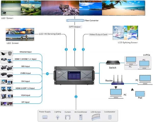
=

LED 4K sending card can load up to 10,400,000 pixels (max. width: 10,240 pixels, max. height: 10,240 pixels).

This card occupies two slots.

  • 16x RJ45 Gigabit Ethernet outputs

−    Bit depth: 8-bit

A single Ethernet port loads up to 650,000 pixels.

−    Bit depth: 10-bit

A single Ethernet port loads up to 320,000 pixels.

−    Backup between Ethernet ports

  • 2x OPT outputs

−    Support both SMF and MMF transmission.

−    OPT 1 copies and outputs the data on Ethernet ports 1–8.

−    OPT 2 copies and outputs the data on Ethernet ports 9–16.

 Note: 

For the optical module connected to the OPT port, you need to order or purchase separately.

H_20xRJ45 sending card

LED 4K sending card can load up to 13,000,000 pixels (max. width: 10,752 pixels, max. height: 10,752 pixels).

This card occupies two slots.

  • 20x RJ45 Gigabit Ethernet outputs

−    Bit depth: 8-bit

A single Ethernet port loads up to 650,000 pixels.

−    Bit depth: 10-bit

A single Ethernet port loads up to 320,000 pixels.

  • Backup between Ethernet ports
H_4xfiber sending card

4x 10G OPT ports

This card can load up to 20,800,000 pixels (max. width: 16,384 pixels, max. height: 16,384 pixels)

  • Independent, copy and backup modes are
  • SM and MM optical modules are both supported, with a transmission distance of up to 10
  • Supports 8-bit and 10-bit
  • The optical module supports SFP+ encapsulation. The supported module specifications include the followings:

−    10G SFP+ SR optical module

−    10G SFP+ LRM optical module

−    10G SFP+ LR optical module

−    10G SFP+ ER optical module

−    10G SFP+ ZR optical module

−    SFP+ CWDM optical module

−    SFP+ DWDM optical module

−    SFP+ BIDI optical module

Independent

Four OPT ports are all used for output and have the same loading capacity. The loading capacity of one port is equal to that of 8 Ethernet ports.

Copy

OPT 1 and OPT 2 are used for main output. OPT 3 copies the output on OPT 1, while OPT 4 copies the output on OPT 2.

Backup

OPT 1 and OPT 2 are used for main output. OPT 3 serves as the backup of OPT 1, while OPT 4 serves as the backup of OPT 2.

 Note:

Four 10G SFP+ LR optical modules are included with the card and are already installed into the OPT ports.

H_2xRJ45+1xHDMI1.3 preview card

  • 2x RJ45 Gigabit Ethernet outputs 

Connect to the network for monitoring the inputs and outputs.

  • 1x HDMI 1.3

Connect to a monitor for displaying the monitoring information.

H_Control Card

GENLOCK

Supports bi-level and tri-level.

  • In: Accept the Genlock signal
  • LOOP: Loop the Genlock signal.
ETHERNET

A Gigabit Ethernet port

  • l Connect to the control PC for communication.
  • l Connect to the router, switch or PC.
  • For Web control and NovaLCT screen configuration
USB 1 & USB 2

2x USB 2.0

  • Update the device program.
  • Import or export the device configuration parameters.

 Note:                                                                                                                                              

The USB connectors cannot provide power for the connected devices.

COM

A serial port that adopts RS232 serial protocol Support for central control system

  • IN: Accept the signal from the central control system.
  • OUT: Loop the signal.

 Note:

The COM port cannot be connected to the network (router or switch) or LED cabinet (receiving card).

Power switch
  • – / ON: Power on the device.
  • O / OFF: Power off the device.

Applications

Dimensions

Specifications

4
Model
H5
Rack Unit
5U
Max. Input Cards
10
Max. Input Channels
40
Max. Output Cards
3
Max. Output Channels
12
Max. Loading Capacity
LED 4K sending card
39 million pixels
H_4xfiber sending card
62.4 million pixels
Max. Layers
48

Electrical

Specifications

Power connector

100–240V~, 50/60Hz, 10A–5A
Note:
The H5 comes with a single power supply. A redundant power supply is optional.

Power consumption
400 W

Operating

Environment

Temperature
0°C to 45°C
Humidity
0% RH to 80% RH, non-condensing

Storage

Environment

Temperature
–10°C to +60°C
Humidity
0% RH to 95% RH, non-condensing

Physical

Specifications

Dimensions
482.6 mm × 532.8 mm × 228.2 mm
Net weight
17 kg (chassis)
Gross weight
21.3 kg (chassis)
Noise Level ( typical at 25°C /77°F)
<45 dB (A)

Packing

Information

Packing box
780 mm × 615 mm × 345 mm
Accessories

1x Power cord

1x RJ45 Ethernet cable 1x Grounding cable

1x HDMI cable

1x Quick Start Guide

1x Certificate of Approval 1x Safety Manual

1x Custom Letter

Video Source Features

Input Connector Color Depth Max. Input Resolution
HDMI 2.0
8-bit
RGB 4:4:4

4096×2160@60Hz

8192×1080@60Hz

YCbCr 4:4:4
YCbCr 4:2:2
YCbCr 4:2:0
4096×2160@60Hz
10-bit
RGB 4:4:4

4096×2160@30Hz

4096×1080@60Hz

YCbCr 4:4:4
YCbCr 4:2:2
4096×2160@60Hz
YCbCr 4:2:0
12-bit
RGB 4:4:4

4096×2160@30Hz

4096×1080@60Hz

YCbCr 4:4:4
YCbCr 4:2:2
4096×2160@60Hz
YCbCr 4:2:0
DP 1.2
8-bit
RGB 4:4:4

4096×2160@60Hz

8192×1080@60Hz

YCbCr 4:4:4
YCbCr 4:2:2
YCbCr 4:2:0
Not supported
10-bit
RGB 4:4:4

4096×2160@30Hz

4096×1080@60Hz

YCbCr 4:4:4
YCbCr 4:2:2
4096×2160@60Hz
YCbCr 4:2:0
Not supported
12-bit
RGB 4:4:4

4096×2160@30Hz

4096×1080@60Hz

YCbCr 4:4:4
YCbCr 4:2:2
4096×2160@60Hz
YCbCr 4:2:0
Not supported
HDMI 1.4 DP 1.1
8-bit
RGB 4:4:4
4096×1080@60Hz
YCbCr 4:4:4
YCbCr 4:2:2
YCbCr 4:2:0
Not supported
10-bit
RGB 4:4:4
2048×1152@60Hz
YCbCr 4:4:4
YCbCr 4:2:2
4096×1080@60Hz
YCbCr 4:2:0
Not supported
12-bit
RGB 4:4:4
2048×1152@60Hz
YCbCr 4:4:4
YCbCr 4:2:2
4096×1080@60Hz
YCbCr 4:2:0
Not supported
HDMI 1.3
8-bit
RGB 4:4:4
2048×1152@60Hz
YCbCr 4:4:4
YCbCr 4:2:2
YCbCr 4:2:0
Not supported
10-bit
RGB 4:4:4
2048×1152@60Hz
YCbCr 4:4:4
YCbCr 4:2:2
YCbCr 4:2:0
Not supported
12-bit
RGB 4:4:4
2048×1152@60Hz
YCbCr 4:4:4
YCbCr 4:2:2
YCbCr 4:2:0
Not supported
SL-DVI
8-bit
RGB 4:4:4
2048×1152@60Hz
DL-DVI
8-bit
RGB 4:4:4
3840×1080@60Hz

VGA CVBS

-

RGB 4:4:4

1920×1080@60Hz

3G-SDI
  • Supports up to inputs. 1920×1080@60Hz video
  • Input resolution and bit depth settings are not allowed.
  • Supports ST-424 (3G) and ST-292 (HD).
12G-SDI
  • Supports up to 4096×2160@60Hz video inputs.
  • Input resolution and bit depth settings are not allowed.
  • Supports ST-2082-1 (12G), ST-2081-1 (6G), ST-424 (3G) and ST-292 (HD).

Notes and Cautions

Notes For Battery

  • The battery is not intended to be replaced.
  • Disposal of a battery into fire or a hot oven, or mechanically crushing or cutting of a battery can result in an explosion.
  • Leaving a battery in an extremely high temperature surrounding environment can result in an explosion or the leakage of flammable liquid or gas.
  • A battery subjected to extremely low air pressure may result in an explosion or the leakage of flammable liquid or gas.

Notes for Installation

When the product needs to be installed on the rack, 8 screws at least M5*8 should be used to fix it. The rack for installation shall bear at least four times the total weight of the mounted equipment.

  1. Elevated Operating Ambient – If installed in a closed or multi-unit rack assembly, the operating ambient temperature of the rack environment may be greater than room ambient. Therefore, consideration should be given to installing the equipment in an environment compatible with the maximum ambient temperature (Tma) specified by the manufacturer.
  2. Reduced Air Flow – Installation of the equipment in a rack should be such that the amount of air flow required for safe operation of the equipment is not compromised.
  3. Mechanical Loading – Mounting of the equipment in the rack should be such that a hazardous condition is not achieved due to uneven mechanical loading.
  4. Circuit Overloading – Consideration should be given to the connection of the equipment to the supply circuit and the effect that overloading of the circuits might have on overcurrent protection and supply wiring. Appropriate consideration of equipment nameplate ratings should be used when addressing this concern.
  5. Reliable Earthing – Reliable earthing of rack-mounted equipment should be maintained. Particular attention should be given to supply connections other than direct connections to the branch circuit (e.g. use of power strips).

FCC Caution

Any changes or modifications not expressly approved by the party responsible for compliance could void the user’s authority to operate the equipment.


This device complies with part 15 of the FCC Rules. Operation is subject to the following two conditions: (1) This device may not cause harmful interference, and (2) this device must accept any interference received, including interference that may cause undesired operation.


Note: This equipment has been tested and found to comply with the limits for a Class A digital device, pursuant to part 15 of the FCC Rules. These limits are designed to provide reasonable protection against harmful interference when the equipment is operated in a commercial environment. This equipment generates, uses, and can radiate radio frequency energy and, if not installed and used in accordance with the instruction manual, may cause harmful interference to radio communications. Operation of this equipment in a residential area is likely to cause harmful interference in which case the user will be required to correct the interference at his own expense.

Brand

Novastar LED

NOVASTAR LED LOGO